To address the challenge of detecting large wing deformation during flight for large high-wing aircraft, a DIC multi-camera dynamic measurement system was used to collect dynamic speckle images of the wing. A large-angle speckle matching algorithm and a real-time vibration compensation calibration method were designed to solve the problems of low image correlation and flight vibration interference.
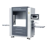
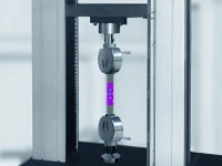
Based on the simulation verification of a 1:10 scale wing test bench, the Xintuo 3D XTDIC-STROBE 3D dynamic measurement system was used for synchronous measurement and accuracy comparison. The verification system's full-field measurement accuracy reached 0.21mm/2m, meeting the requirements for wing deflection monitoring under flight loads, and providing a high-precision full-field dynamic deformation measurement solution for aircraft aeroelastic analysis.
在飛行過(guò)程中機(jī)翼大撓度變形檢測(cè)")
1. Background of the Project
Large, high-wing aircraft experience significant aerodynamic loads on their wings during flight. Typically, the wingtip of a large aircraft with a wingspan of 40-50 meters experiences upward and downward fluctuations exceeding 1 meter. Due to the significant wing deformation, it is necessary to obtain three-dimensional data on the wing deformation distribution of large aircraft during flight.
Traditional strain gauge methods (measurement point density ≤ 20 points/m2) struggle to capture full-field strain distribution, while photogrammetry is susceptible to vibration and viewing angle limitations. NASA previously used DIC technology during A380 wing testing to measure deformation in selected wing regions, but faced a high matching failure rate at high inclination angles (>40°).
Using a distributed camera layout, a dynamic calibration compensation algorithm, and a real-time vibration compensation calibration method, we achieve accurate reconstruction of the full-field deformation field under complex motion, providing valuable guidance for on-board measurement.
2. Problems and Solutions of Wing Dynamic Measurement
Difficulty 1: Large tilt angle deformation leads to low image correlation
The wing can deflect by up to 40-50° during flight, and the camera's viewing angle is severely tilted, resulting in severe deformation of the speckle image and distortion of the grayscale distribution. The traditional DIC algorithm has a matching failure rate of >30%, and fracture areas appear in the displacement field.
Large deformation weak correlation images collected by high-position camera and low-position camera
Technical Solution:
Using a high-angle weakly correlated speckle matching method, the reference image sequence and the target image sequence captured by the camera are used as two sets of image sequences. Matching operations are performed on the reference subset and the target subset within their own image sequences. This method provides reliable initial values, making the linear iterative least squares algorithm faster, more accurate, and more robust.
A multi-level hierarchical matching algorithm
Based on feature point-guided progressive matching, global large deformations are decomposed into local rigid body motions and small deformation iterations.
Multi-camera perspective fusion
A "high-low" dual-camera array (vertical tail + fuselage arrangement) covers a ±60° field of view. Calibration is combined with bundle adjustment to optimize global pose. The four-camera system increases blind spot coverage from 62% to 98%.
Large-angle weak-correlation speckle matching method
Difficulty 2: Flight vibration causes measurement reference drift
During actual flight measurement, the aircraft is affected by high-speed airflow, and the tail part where the measurement camera is installed will vibrate, requiring real-time dynamic correction of the position and attitude of the measurement camera.
Technical Solution:
Camera Dynamic Calibration
The back of the monoplane serves as a rigid, fixed reference. Using the single-image resection method, the position and pose of the reference camera in the world coordinate system, i.e., the camera's exterior orientation elements, are calculated in real time.
Using pre-calibrated relative exterior parameters, the absolute exterior parameters of the conjugate measurement camera at each frame are calculated, achieving dynamic calibration of the measurement camera.
Camera Vibration Compensation
During calibration, all camera interior orientation elements are first calibrated, and the relative positional relationships between the cameras are known. Given the exterior parameters of any camera, the absolute exterior parameters of the conjugate camera can be calculated using the relative exterior parameters.
Schematic diagram of camera vibration compensation
3.3D Full-Field Dynamic Deformation Measurement of Wings
According to the structural characteristics of high-wing aircraft, a measurement scheme for the three-dimensional full-field deformation of the wing is designed.
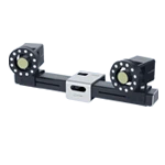
Camera installation prpposal
Measurement Process and Results
After calibrating the internal and external parameters, wing deformation images were collected. The camera position was then inverted in real time based on the 3D coordinates of fixed points on the back of the aircraft. Full-field wing deformation information was then calculated.
The measurement accuracy of this study was verified using the Xintuo 3D XTDIC-STROBE system. The full-field solution accuracy was compared by simultaneously calculating the 3D coordinates of key points. The system achieves a measurement accuracy of 0.01mm on a 300mm x 400mm format. The results can be used to evaluate the accuracy of full-field wing deformation measurements.
4. Flight Test Verification
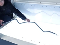
A simulation test environment was established, using a 1:10 scaled-down aircraft model as the measurement target, to verify the feasibility and effectiveness of the measurement solution.
To assess measurement accuracy, the XYOP3D XTDIC-STROBE system was used to synchronously track landmarks on the wing surface. The proposed measurement accuracy was verified by comparing and analyzing the dynamic 3D coordinates of the landmarks.
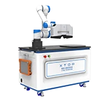
Wing deformation measurement test platform
Simulated Measurement Results
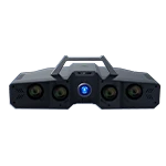
A six-camera probe and two XTDIC-STROBE systems synchronously captured images. Finally, a full-field deformation solution was performed to obtain full-field displacement and deformation results of the wing.
The displacement results of four key points were compared with those of the XTDIC-STROBE system. The average absolute value of the difference was analyzed to determine the accuracy of the full-field wing deformation measurement system. The displacement measurement error was less than 0.21 mm/2 m.
Key point measurement accuracy
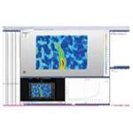
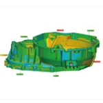
The chromatograms of the three-dimensional displacement field of the wing deformation under different shooting conditions are shown in the figure:
Three-dimensional full-field deformation chromatogram of the wing
5. Analysis Conclusion
A three-dimensional, full-field deformation measurement scheme for high-wing aircraft wings during actual flight was proposed. A dedicated measurement system was developed and simulated measurements were performed. Simultaneous measurements and accuracy comparisons were performed using the Xintuo 3D XTDIC-STROBE 3D dynamic deformation measurement system. Error results were analyzed graphically.
1) The displacement measurement error of the experimental wing was less than 0.21 mm/2 m.
2) The simulation measurement results demonstrated the effectiveness and feasibility of the proposed DIC measurement scheme.
This research provides valuable reference for practical engineering measurement of high-wing aircraft wing deformation during flight.
Excerpt from: [Wei Bin, Liang Jin, Ren Maodong, State Key Laboratory of Mechanical Manufacturing Systems Engineering, School of Mechanical Engineering, Xi'an Jiaotong University, "Three-Dimensional Full-Field Deformation Measurement Scheme for Large High-Wing Aircraft Wings"]


 Watch Video


與低位相機(jī)采集的大變形弱相關(guān)圖像")
散斑匹配方法原理示意圖")
振動(dòng)補(bǔ)償示意圖")
態(tài)測(cè)量dic相機(jī)安裝方案")
用于機(jī)翼變形測(cè)量試驗(yàn)平臺(tái)")
用于機(jī)翼變形測(cè)量精度情況")
翼三維全場(chǎng)變形色譜云圖")


